As a supplier of Continuously Transposed Conductors (CTCs), I’ve had the privilege of delving deep into the world of these remarkable electrical components. One of the most crucial aspects that we often discuss with our clients is the electromagnetic – interference (EMI) characteristics of CTCs. In this blog, I aim to unpack these characteristics, shedding light on why they are so important and how they impact various applications. Continuously Transposed Conductors
Understanding Continuously Transposed Conductors
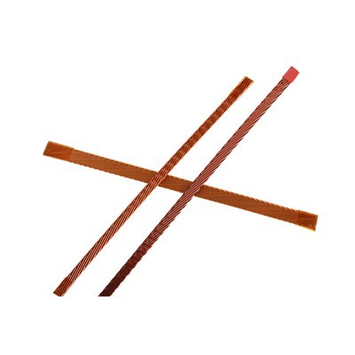
Before we dive into the EMI characteristics, let’s briefly recap what CTCs are. Continuously Transposed Conductors are multi – strand conductors that undergo a continuous transposition process. This means that each individual strand within the conductor takes all possible positions in the cross – section over a specific transposition length. The primary purpose of this transposition is to equalize the electrical and magnetic properties of each strand, reducing circulating currents and improving the overall performance of the conductor.
CTCs are widely used in high – power transformers, reactors, and other electrical equipment. Their unique structure allows for efficient power transmission, lower losses, and better thermal management compared to traditional conductors.
EMI: A Fundamental Concern
Electromagnetic interference (EMI) refers to the disturbance that affects an electrical circuit due to either electromagnetic induction or electromagnetic radiation emitted from an external source. In electrical systems, EMI can cause a range of problems, from minor disruptions in signal quality to complete system failures.
In the context of CTCs, EMI is a significant concern because these conductors are often used in high – voltage and high – power applications where electromagnetic fields are intense. Understanding the EMI characteristics of CTCs is crucial for ensuring the reliable operation of the electrical equipment in which they are installed.
EMI Characteristics of Continuously Transposed Conductors
1. Low Circulating Currents
One of the key EMI – related benefits of CTCs is their ability to minimize circulating currents. In a non – transposed conductor, the magnetic field generated by the current flowing through the conductor can induce a voltage in the individual strands. This induced voltage can cause circulating currents to flow between the strands, leading to additional power losses and increased electromagnetic radiation.
However, in a CTC, the continuous transposition ensures that each strand experiences the same average magnetic field over the transposition length. As a result, the induced voltages in the strands are equalized, and the circulating currents are significantly reduced. This reduction in circulating currents not only improves the efficiency of the conductor but also reduces the electromagnetic radiation associated with these currents, thereby minimizing EMI.
2. Symmetrical Magnetic Fields
The transposition process in CTCs also creates a more symmetrical magnetic field distribution around the conductor. In a typical non – transposed conductor, the magnetic field can be unevenly distributed, leading to localized areas of high magnetic flux density. These areas of high flux density can act as sources of electromagnetic radiation, contributing to EMI.
In contrast, the continuous transposition of the strands in a CTC ensures that the magnetic field is more evenly distributed around the conductor. This symmetrical magnetic field distribution helps to reduce the overall electromagnetic radiation from the conductor, thus improving its EMI performance.
3. Shielding Effect
The compact structure of CTCs provides a certain degree of shielding against external electromagnetic fields. The multiple strands in a CTC are closely packed together, and the outer layers of the strands can act as a shield to protect the inner strands from external electromagnetic interference.
This shielding effect is particularly important in applications where the CTCs are exposed to strong external electromagnetic fields, such as in power substations or near high – voltage transmission lines. By reducing the susceptibility of the conductor to external EMI, the CTCs can maintain their electrical performance and reliability.
4. Frequency – Dependent Behavior
The EMI characteristics of CTCs are also frequency – dependent. At low frequencies, the primary source of EMI is the magnetic field generated by the current flowing through the conductor. As the frequency increases, the skin effect becomes more pronounced, causing the current to concentrate near the surface of the conductor. This concentration of current can lead to an increase in the electromagnetic radiation from the conductor and also affect the distribution of the magnetic field.
In addition, at high frequencies, the capacitive coupling between the strands in the CTC can become significant. This capacitive coupling can cause additional currents to flow between the strands, leading to increased EMI. Therefore, when designing electrical systems using CTCs, it is important to consider the frequency range of the operating currents and take appropriate measures to mitigate EMI at different frequencies.
Impact of EMI Characteristics on Applications
1. High – Power Transformers
In high – power transformers, CTCs are used in the windings to improve the efficiency and performance of the transformer. The low circulating currents and symmetrical magnetic fields of CTCs help to reduce the power losses and electromagnetic radiation from the transformer windings. This not only improves the energy efficiency of the transformer but also reduces the interference with other electrical equipment in the vicinity.
2. Reactors
CTCs are also commonly used in reactors, which are used to control the current and voltage in electrical systems. The EMI characteristics of CTCs play a crucial role in ensuring the stable operation of reactors. By reducing the electromagnetic radiation from the reactor windings, the CTCs help to minimize the interference with other components in the electrical system, such as control circuits and communication devices.
3. Renewable Energy Systems
In renewable energy systems, such as wind turbines and solar power plants, CTCs are used in the power generation and transmission equipment. These systems often operate in harsh electromagnetic environments, and the EMI characteristics of CTCs are essential for ensuring the reliable operation of the equipment. The shielding effect of CTCs helps to protect the conductors from external electromagnetic interference, while the low EMI emissions from the CTCs prevent interference with other components in the renewable energy system.
Mitigating EMI in CTC Applications
While CTCs have inherent EMI – friendly characteristics, there are still situations where additional measures may be required to further mitigate EMI. Some common methods for reducing EMI in CTC applications include:
1. Proper Grounding
Proper grounding of the CTCs and the associated electrical equipment is essential for reducing EMI. By providing a low – impedance path for the electromagnetic currents to flow to the ground, grounding helps to minimize the electromagnetic radiation from the conductors and the equipment.
2. Use of Shielding Materials
In some applications, the use of shielding materials, such as conductive foils or braids, can be effective in reducing EMI. These shielding materials can be wrapped around the CTCs to provide an additional layer of protection against external electromagnetic fields and to contain the electromagnetic radiation from the conductors.
3. Filtering
The use of filters, such as electromagnetic interference filters, can be used to reduce the EMI in the electrical system. These filters are designed to block or attenuate the unwanted electromagnetic frequencies, while allowing the desired frequencies to pass through.
Conclusion
As a supplier of Continuously Transposed Conductors, I am well – aware of the importance of the EMI characteristics of these conductors. The unique structure of CTCs, with their continuous transposition of strands, provides several advantages in terms of reducing EMI, including low circulating currents, symmetrical magnetic fields, and a certain degree of shielding.
However, it is also important to recognize that the EMI characteristics of CTCs are complex and frequency – dependent, and additional measures may be required to mitigate EMI in specific applications. By understanding the EMI characteristics of CTCs and taking appropriate measures to control EMI, we can ensure the reliable operation of electrical equipment and the efficient transmission of power.
Continuously Transposed Conductors If you are in the market for high – quality Continuously Transposed Conductors and want to discuss how our products can meet your specific EMI requirements, I encourage you to reach out to our sales team. We are committed to providing you with the best solutions for your electrical applications.
References
- Grover, F. W. (1946). Inductance Calculations: Working Formulas and Tables. Dover Publications.
- Paul, C. R. (2006). Introduction to Electromagnetic Compatibility. John Wiley & Sons.
- Sullivan, C. R. (2008). Electromagnetic Compatibility Engineering. Wiley – Interscience.
Tianjin Jingwei Power Technology Co., Ltd.
As one of the most professional continuously transposed conductors manufacturers and suppliers in China, we’re featured by quality products and good service. Please rest assured to buy durable continuously transposed conductors made in China here from our factory. Contact us for more details.
Address: No.1 Chuangxin Rd. Xiaozhan Industrial Park, Jinnan District, Tianjin, China
E-mail: info@jwdc.cn
WebSite: https://www.jw-dcs.com/
